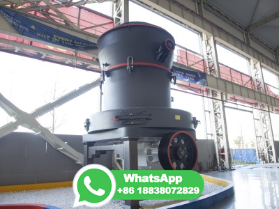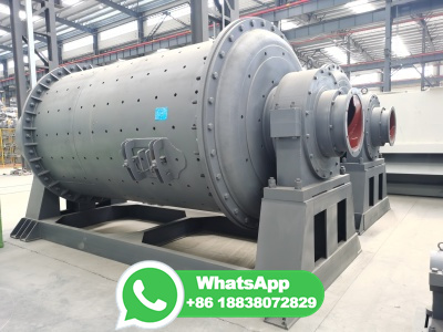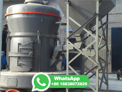
Design and simulation of gear box for stone crushing ball mill
Abstract This research paper contains the design aspects and analysis of the gear box used in the ball mill. The ball mill is used for the conversion of the raw stone material into the powder form by using steel balls inside.